Showing posts with label English. Show all posts

Tuesday, July 12, 2011

Let's begin

SEE THIS POST IN POLISH

As was seen in previous post, the script to automatically develop elements in Sketchup works.
But since the programming is not the main part of ​​this blog, I decided to start with something more practical.
So we go with the Su-17M. Why this plane? Hmmm ...
It seems to me that a simple fuselage and overall shape decided ...
The place, which surely will bring the problems will be wings.
I think intensively over the folding mechanism of the wings. Maybe I will able to synchronize both sides.


The first stage of design is documentation. Aligning views (up-down-front-page) and appropriate scaling of them is made in any graphics software.
To make modelling easier I removed the background in each of the view and saved it as PNG, which allowed to maintain transparency. Then I inserted everything into SketchUp.

The next step was to trace the shape of the fuselage in views from the top and side. I chose this way of modeling, since the individual sections of the fuselage, available in this set of plans do not fit well to top and side view of plane. So I decided to approach the fuselage modelling from another direction. Because the fuselage sections are approximately round - elliptical, I will draw hull first and then create it's cross-sections.
The outline of the fuselage is dwith BZ CURVES - Sketchup extension that allows you to draw spines and other curves.
I pulled both shapes and made intersection. Then I drew vertical planes in places where I planned bulkheads and after another intersection and removing not necesary geometry I received a series of rectangles.
In the individual rectangles I drew elipses. To do  this, I used to be another extension for SketchUp: TOOLS ON SURFACES.

Fuselage was constructed on defined sections using yet another Sketchup extension: CURVILOFT.
You can also try a different script: SKIN.
Here you can see the effect already made with the wings.


Construction of wings in the next post.

Tuesday, July 5, 2011

Good bye Excel , Welcome Ruby

SEE THIS POST IN POLISH
So... Here comes the time, when you have to lower your head and admit: I was wrong.

I was wrong, thinking that Excel or other calculation sheet will be the most universal way to unroll parts...

I was also wrong, thinking that learning another programming language is a bit too much...

I am wrong and probably will be wrong on several occasions, but the work continues , but this time only in Sketchup and in RUBY :


To Be Continued

Sunday, May 22, 2011

Video !!! How it works so far.

SEE THIS POST IN POLISH
Welcome again.
It has been a while, but I am back online.
So today a small preview of how it works so far.No voice over - My voice just sounds strange :D
First video is pure Sketchup.
We have 2 definition curves created with Bezier curves.
Note that precision of both curves is set to the same value (50 parts).
There is also another closed curve that will be used as a definition of camouflage.
First we create our surface with another ruby script - skin.
You can see what settings I used.
Then we pull our camouflage definition, and create intersection with our surface.
When cleared from all not necessary parts we can see camo lines on our surface.
Next part is to export points to a files, one for top curve, one for bottom curve and one for all camo points.


Second video is first part of excel calculations.
First we import points for definition curves. On a preview you can see that points are numbered and this will be used for sorting. Calculations are made in a way that curves should go anticlockwise. So our starting point is at bottom, and first point should be where nor point 51 is.Next point would be where now 50's are. Also You can see at the top that on curve 2 ( blue ), there is something wrong ( look at the points 2,1 and 3)
So we go back to curves input , and set points nr 51 on both curves as 1 and points 50 as 2 , after resorting points on first curve You can seethe effect ( best on 3d preview).
Resorting second curve gets us our developer surface.
We can import camouflage line points.
(Error message occurs because there is no points data available.)
We run a macro to develop points onto surface , and after some time we get all points developed.
Time it takes is dependent on number of points to develop and number of points on definition curves.
When all calculations are done we can export all points to CSV file to get it to Sketchup again.


Third part next time.

Friday, April 15, 2011

Progress with work

SEE THIS POST IN POLISH

Not so much time to write here, but it is steady going forward.

Sheet 1 - Definition curves data.


Sheet 1 - Development Preview, Definition curves in head view and in axonometry.
Sheet 2 - More detailed head-on view of definition curves . This will be used to properly orientate our part . 


Sheet 3 - Input data for points on the surface .


Sheet 3 - Preview of surface points in axonometry .
 Sheet 3 - Preview of developed surface points .
In fact it s possible to export this data to Sketchup and draw an developed element . But at this moment there is no Sketchup plugin to automatically fit curve to set of points , so You would have to draw an curve point by point.
At this moment work is concentrated on work arount for this .

To be continued . . .

Friday, April 1, 2011

Excel automation


Lets put what we already know into practice :
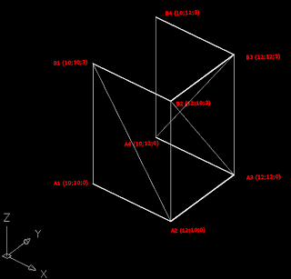
Example 1
This is our example .  Quite simple it is, but it will show every step and because all the points have integer coordinates it is simple to control calculation steps. 

Distances between points
From point coordinates we can calculate distances as on the picture to the left . All the diagonal lines have the same length .
r1 , r2 , r3 and r4 for first pair of points
For calculation of first pair of points we define r1, r2 , r3 and r4 , as on a picture to the left .


r1 , r2 , r3 and r4 for second pair of points
For a second pair we do the same  and we can see all the marked lines on a picture .


Developed surface from example 1
As a result we should get unrolled surface with a point coordinates as on a picture .
Formulas
All the calculations we perform in spreadsheet ( Excel , OpeOffice.org Calc or another ).
This is a simple version of such a spreadsheet .
You can see the formulas , and below i will give explanation of all of them .
Only first line is inputted, rest of the formulas will be automatically inputted using fill handle .


Cell A3 : Point number
Cells B3-D3 : Coordinates of points in curve A
Cells E3-G3: Coordinates of points in curve A
Cell H3 : Distance between point A1 and A2 [r1]
Cell I3 : Distance between point A2 and B1 [r2]
Cell J3 : Distance between point A1 and B1 [D]
Cell K3 : Difference between x coordinates of points A'1 and B'1 [Dx]
Cell L3 : Difference between y coordinates of points A'1 and B'1 [Dy]
Cell M3 : Value of a based on r1, r2 and D [a]
Cell N3 : Value of h based on r1and a [h]
Cell O3 : Distance between point A2 and B2 [r3]
Cell P3 : Distance between point B1 and B2 [r4]
Cell Q3 : Distance between point A2 and B1 [D]
Cell R3 : Difference between x coordinates of points A'2 and B'1 [Dx]
Cell S3 : Difference between y coordinates of points A'2 and B'1 [Dy]
Cell T3 : Value of a based on r3, r4 and D [a]
Cell U3 : Value of h based on r3and a [h]
Cells V3-X3 : Starting point of developed surface (coordinates x, y, z) [point A'1]
Cells Y3-AA3 : point B'1 , coordinate  x = coordinate x of point A'1 plus value D from cell J3
                         Coordinates y and z are the same as of point A'1
Cells V4-X4 : Coordinates x and y of point A'2 , based on r1 , r2 , h , a , Dx , Dy and D.
                       Coordinate z is the same as z of point A'1
Cells Y4-AA4 : Coordinates x and y of point B'2 , based on r3 , r4 , h , a , Dx , Dy and D.
                       Coordinate z is the same as z of point B'1

Calculated example 1
Our example calculated with a spreadsheet .
We can of course expand our spreadsheet for more points, and add for example an preview of developed surface .
Example 2 . 
Curves, points, triangles, surface and developed surface
Here we can see two definition curves as a splines, points generated on the curves , triangles spanned on the points , generated surface and developed surface .
Coordinates of the points were exported to excel file , and then inputted into our spreadsheet .
Then calculated developed point were exported and on base of those was developed surface drawn .

Calculated example 2

To be continued ...


Tuesday, March 29, 2011

An advantage of using Sketchup

SEE THIS POST IN POLISH

Why Sketchup ?
The biggest advantage :  it's free .
You can also extend it's capabilities using multiple Ruby scripts .
From a point of view of a model designer, RHINO has 2 very interesting functions . One is developing of surfaces , and as a bonus Rhino can also develop a lines and curves that are on those surfaces . Second function is a possibility to project curves onto a surface .

How does it look in Sketchup  ?
 
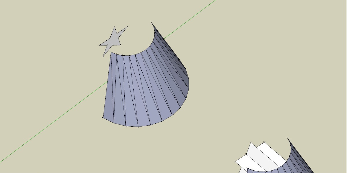
Surface and an element to project
Here we have an surface with an element we want to project .


Pushed / pulled surface
We push / pull this element , and then make an intersection between those two .


Result of intersection
We erase pulled element and on our surface we get projected shape .


In sketchup all the curves are represented as a set of lines or a polyline . At first it can look as an disadvantage , but is it so ?
On a picture abowe all the points  (ends of lines) ar bolded . How can we use it ? We can calculate a distance between every point an 2 points of a triangle , and use our algorythm to find this point on a developed surface.
Points inside triangle


To be continued . . .

Monday, March 28, 2011

From 3D to 2D with algebra


To write a developing algorithm we need to get familiar with 2 topics from mathematical algebra .

3D coordinates and length of triangle sides
First we need to know all 3 sides of triangle .
A triangle can be defined with 3 points . And every point can be described with 3 coordinates (x,y,z) .
Distance between two points is equal to square root from sum of squared differences between point coordinates . See picture .


Construction
 Next step is made in 2 dimensions . First we define a line between two points A and B . distance between those points is equal to length of a first side of triangle ( D on a picture ) . Other sides of a triangle have lengths of  r1 and  r2 . We are looking for point C with coordinates (xC; yC) .

First step is to find point S .
From Pythagorean theorem for triangles ACS and BCS we:get :
r1² = h² + a²
r2² = h² + b²
From difference between those two equations :
r1² - r2² = a² - b²
r1² -r2² = (a+b) * (a-b)
And because D = a + b  and  b = D - a
r1² -r2² = D * (2a-D)
Therefore :
a = (r1² -r2² +D²) / 2D

Point S has coordinates :
xS = x1 + (Dx * a) / D
yS = y1 + (Dy * a) / D

When we know a we can also calculate h : h = √(r1² - a²)
we can also write down two dependencies :
Dy / D = dx / h  =>  dx = - (Dy * h ) / D
( negative sign tells us that if Dy is positive(point B is above point A), then point C is to the left from point S and vice-verso )
Dx / D = dy / h  =>  dy = (Dx * h ) / D

Last step is getting coordinates of point C :
xC = xS + dx = x1 + (Dx * a) / D - (Dy * h ) / D = x1 + (Dx * a - Dy * h ) / D
yC = yS + dy = y1 + (Dy * a) / D + (Dx * h ) / D = y1 + (Dy * a + Dx * h ) / D

There is also second possible point C' that is situated below line AB
xC' = xS + dx = x1 + (Dx * a) / D + (Dy * h ) / D = x1 + (Dx * a + Dy * h ) / D
yC' = yS + dy = y1 + (Dy * a) / D - (Dx * h ) / D = y1 + (Dy * a - Dx * h ) / D

To be continued ...

Friday, March 25, 2011

My unrolling theory

ZOBACZ TEN POST PO POLSKU

A developable surface is a ruled surface which in every point has a Gaussian curvature equal to 0 .

That is a definition. In fact that means that developable surface can be developed to a plane without stretching or cutting .
 
Cone side development .

An example can be side of a cone or a cylinder .
You can also say that cone is an pyramid with an infinite number of base sides .Cylinder is a prism with an infinite count of base sides . That means that every prism or pyramid can be developed .
That leads to the conclusion that surface is developable if it consist from multiple flat surfaces , and every surface is connected to others with not more than 2 sides .

Surfaces spanned between spline an arc,
and polylines that interpolate basic curves.
Surfaces modelled with quads and triangles.
So if You have two curves, You can interpolate it with a polylines with the same sides count . On these polylines You can create a surface that consist from multiple quadrangles .
But not every quadrangle must be flat . To solve this problem, You can divide every quadrangle into two triangles , which solves the problem because every triangle is a flat figure .

How to develop 3-dimensional triangulated surface ?


Definition curves, spanned surface and it's development .

We have 2 polylines that will define our surface, lets mark their points with A1-A5 and B1-B5 .
Create a triangulated surface spanned on those 2 polylines ( see picture to the left ) . Such a surface you can develop using simple geometrical construction.
Construction  of a triangle using 3 known sides .
If You know length of all 3 sides of a triangle , You can draw one side , and then draw from both ends arcs with a radios equal to length of other sides . Intersection between those arcs gives You third point of a triangle. If You repeat the same construction for every triangle , in the end You get a developed surface .


Next task is to make the whole process automatic ?

To be continued ...

Wednesday, March 23, 2011

Designing card scale model

ZOBACZ TEN POST PO POLSKU.

Designing a scale card model in 3D can be divided into 6 stages.
  1. Collecting information about Your model.
  2. Modelling in 3D
  3. Unrolling parts
  4. Graphical design (color)
  5. Test assembly
  6. Eventually corrections.
Stage 1 doesn't need more explanations, but the better references can You get the better.
Stage 2 Is modelling in 3d in a way that it would be possible to unroll all the parts without too much deformations. Most commonly used software for this task is RHINO, because it has a an inbuilt unrolling function, so it is possible do do stages 2 and 3 in one software.
Stage 4 is exporting unrolled parts to a graphic software ( most commonly used is COREL), where You can add additional elements as lines, camo end markings etc.
Stage 5 is a big test if it is possiblle to put it all together .
If not, then in stage 6 You can adjust Your design , that means remodelling or changing Your model (see stage 2) .

RHINO and COREL have one major drawback : PRICE .

And there is an idea for this blog - is it possible do do it with a freeware software ?

To be continued . . .